Developing a structural calculation agent on top of a verified solver*
aFacultad de Ingeniería, Universidad de Buenos Aires (FIUBA), Argentina
bLambdaClass and Ergodic Group
bchesta@fi.uba.ar, rbertero@fi.uba.ar, federico@lambdaclass.com, dkingston@fi.uba.ar
Abstract
The structural engineer's workflow remains essentially manual despite decades of software evolution. Generative AI can transform that practice, but a language model cannot guarantee numerical correctness or code compliance. The thesis of this work is that an AI agent is reliable only if it operates as an orchestrator over a verified solver, without generating numerical results on its own. A conversational agent is presented that translates the engineer's intent into modeling actions on a structural solver verified through benchmarks and reference cases, performs code verification in accordance with CIRSOC 201 and 301, and generates traceable calculation reports. A progressive roadmap is outlined: in the short term, assistance in modeling and verification; in the medium term, design iteration with the solver in the loop; in the long term, an interface where the engineer decides while the agent proposes, calculates, verifies, and documents. It is concluded that the incorporation of AI into structural engineering is viable when it relies on verified structural analysis tools and preserves the traceability required for professional practice.
Keywords: artificial intelligence, structural agent, conversational modeling, verified solver
1Introduction
1.1Computer-aided engineering
Computer-aided design and analysis let engineers automate routine tasks, speed up computation and study scenarios, freeing time for analysis and decision-making, with the resulting reduction in engineering and construction time and cost. Those programs were conceived for a human user operating a graphical interface. The engineer knows the fundamentals of the discipline and judges results critically, but getting to them involves a learning curve that is not trivial: one has to master the interface, understand how the program presents its output and, when that output does not fit the analysis one wants to carry out, export the data and resort to one's own post-processing.
It is worth being precise about where the cost lies today. Decades of evolution of commercial software made the strictly numerical part of the analysis fast. Assembling a stiffness matrix and solving a linear system is a well-understood and computationally cheap problem. The engineer's time goes into building the model, rebuilding it every time the architecture changes, defining loads and combinations, checking member by member against the code, and producing the calculation report and the drawings. Calculation is the fast part; the bottleneck is the manual, repetitive scaffolding around it.
Added to that friction is a barrier of cost and access. In Argentina and the region, practice relies largely on proprietary software whose professional licenses cost several thousand dollars a year per seat. Programs such as SAP2000, ETABS, STAAD.Pro, RAM Elements and RFEM dominate the professional market [1], and CYPECAD is widespread for houses and buildings with simple structures, while open-source alternatives such as OpenSees [2] or Code_Aster [3] require scripting in languages such as Tcl or Python, offer no modern graphical interface and do not implement the Argentine codes.
1.2The arrival of AI
Generative artificial intelligence (AI) is changing that landscape, both in how software is written and in how it is used. An agent built on a language model lets the engineer state an objective in natural language and lets the system act as an assistant: it prepares the data for a simulation, interacts with the analysis program and transforms the output so the engineer can analyze it and decide. A growing trend treats these models as general-purpose reasoning engines, able to move from image recognition to writing, computation or engineering design through the same conversational interface [4, 5].
That versatility has a precise limit. A language model generates probabilistic text: it knows nothing of the laws of physics or of how real systems behave, and it can hallucinate, returning answers that sound plausible but are incoherent. In structural analysis the risk is concrete: modeling demands spatial reasoning and topological consistency, and multi-step modeling is prone to hallucinations and accumulated errors, limitations documented for current models [6, 7]. An agent therefore cannot be used unsupervised, and critical analysis and the decision remain with the engineer.
One way to bound that risk is not to ask the model to calculate. Instead of improving it until it "calculates well", calculation is taken away from it: the agent proposes designs and scenarios, but for a result to be valid it must go through an analysis program that the agent cannot modify and that holds the physics of the problem. The model decides which deterministic tool to invoke and with which parameters, and integrates what that tool returns; it never originates a number or invents geometry. That is the precise sense of agent adopted in this work (what is known as tool use or function calling, §2.1): a system that orchestrates, not one that solves.
1.3Professional practice
This restriction is not a software-engineering precaution; it stems from how professional practice works. Every structural result carries a signature, with the authorship and legal liability that follow from it. The number that sizes a column is not just another piece of data: it is a commitment by the licensed engineer who signs it. An agent that provides unverified results adds no engineering value, since it shifts onto the professional the risk of signing a calculation nobody checked. The usefulness of AI in this domain therefore depends on two conditions. The first is that the correctness of the result be a property of the solver and not of the language model. The second is that the system preserve the traceability that the signature demands, so that every reported value can be traced back to the verified calculation that produced it, and not to a statement by the model.
1.4Contribution and organization of the paper
Separating a model that orchestrates from a deterministic solver that calculates is not an isolated proposal of this work. It is the dominant pattern in the recent literature on engineering agents (§2.2), and it is adopted here deliberately as an established design principle rather than presented as a finding of our own. What sets Stabileo apart from those precedents are four design decisions that, to the best of the authors' knowledge, no previous system combines:
- Typed actions instead of free code generation. The precedents have the model generate Python code (for example, OpenSeesPy scripts) that is then run against an external solver [7, 8]. Stabileo restricts the agent's output to a closed set of typed calls with explicit input and output contracts (for example, an action that creates a frame with its span and height as parameters), validated against a schema before they run. It is a narrower and more auditable boundary than arbitrary code.
- Its own, extensively tested solver rather than a wrapper around third-party software. Stabileo's engine is a finite element engine written from scratch in Rust (a high-performance language), with its own verification suite against analytical solutions and reference benchmarks, whereas the precedents wrap existing tools.
- Native code compliance. The system implements verification to the Argentine codes CIRSOC 201 [9] and CIRSOC 301 [10], which no open-source software implements natively (their degree of maturity is detailed in §5.2).
- Runs in the browser, with no local installation. The engine compiles to WebAssembly and runs locally in the user's browser, with no calculation server.
On that basis, the concrete contributions of this work are three. First, an architecture in which the agent orchestrates and a verified solver calculates, called here the determinism boundary (§3), whose scope and guarantees are stated precisely (§3.2). Second, its realization in Stabileo, an open-source platform that integrates the Rust solver compiled to WebAssembly, CIRSOC verification, a multi-provider conversational agent and the generation of calculation reports and drawings, all running in the browser (§5). Third, an evaluation through end-to-end case studies whose results are actual solver outputs, also checked against a commercial program, together with an explicit account of what is validated and what remains future work (§6).
The rest of the paper is organized as follows: §2 places this work within the literature on tool use by language models and on agents built on engineering solvers; §3 defines the architecture and the determinism boundary; §4 lays out the path towards a proven solver through formal verification and fuzzing; §5 describes the implementation in Stabileo; §6 goes through end-to-end case studies; §7 discusses the impact on professional practice; §8 covers limitations and future work; and §9 closes with the conclusions.
2Related work
2.1Tool use by language models (tool use / function calling)
A recent line of work gives language models the ability to invoke external tools instead of solving everything internally. ReAct interleaves reasoning and actions, letting the model consult tools while solving a task [11]. Toolformer, for example, shows that a model can learn, in a self-supervised way, when and how to call external APIs [12]. Gorilla connects a model to a large set of APIs and reduces invalid invocations [13]. Current providers expose native function calling, in which the model emits a typed call that an external system executes. The common thread is that the model does not produce the final answer: it routes to a tool and composes its output. Stabileo adopts this pattern, with the particularity that the tools are a structural solver and code-verification modules.
2.2Agents with a solver or verifier as the source of truth
A related pattern delegates the part that requires correctness to a deterministic component. Program-aided approaches have the model generate a program whose execution, and not the model itself, produces the numerical result [14]. The generalization is to couple the model to a symbolic or numerical solver so that correctness is a property of the verifier and not of the language. This work applies that idea to structural analysis: the verified solver and the CIRSOC verification modules are the source of truth, and the agent is confined to interpreting intent, orchestrating execution and explaining results already calculated.
2.3AI applied to structural engineering and AEC
Prior work on AI in architecture, engineering and construction (AEC) can be arranged in three generations. The first (2010–2020) applied neural networks to specific problems, such as predicting concrete strength, detecting damage or accelerating topology optimization with convolutional networks [15]. The second (2020–2024) used neural operators and graph neural networks to partially replace the finite element method, with speed-ups of up to three orders of magnitude but limited to parametric families of geometries [16, 17]. The third (2024–present) uses language models as a conversational interface and as an orchestration agent over existing engineering tools [4, 5]. Stabileo belongs to this third generation: it does not use AI to approximate the physics, but to orchestrate a verified solver.
2.4Positioning: what this work contributes
Table 1 summarizes qualitatively some of the most widely used structural analysis tools worldwide. What sets Stabileo apart is not each feature on its own, but their integration: to the best of the authors' knowledge, no tool brings together native CIRSOC verification, an orchestrating AI agent and an open-source core.
| Tool | Type | CIRSOC | Browser | Built-in AI |
|---|---|---|---|---|
| SAP2000 / ETABS | Commercial | Partial | No | No |
| STAAD.Pro | Commercial | No | No | No |
| RAM Elements | Commercial | No | No | No |
| RFEM / RSTAB | Commercial | No | No | No |
| CYPECAD | Commercial | Yes | No | No |
| OpenSees | Open source | No | No | No |
| Code_Aster | Open source | No | No | No |
| SkyCiv | SaaS | No | Yes | Partial |
| Stabileo | Open source | Yes | Yes | Yes |
3Agent architecture: the determinism boundary
3.1Layers: intent, deterministic computation, documentation
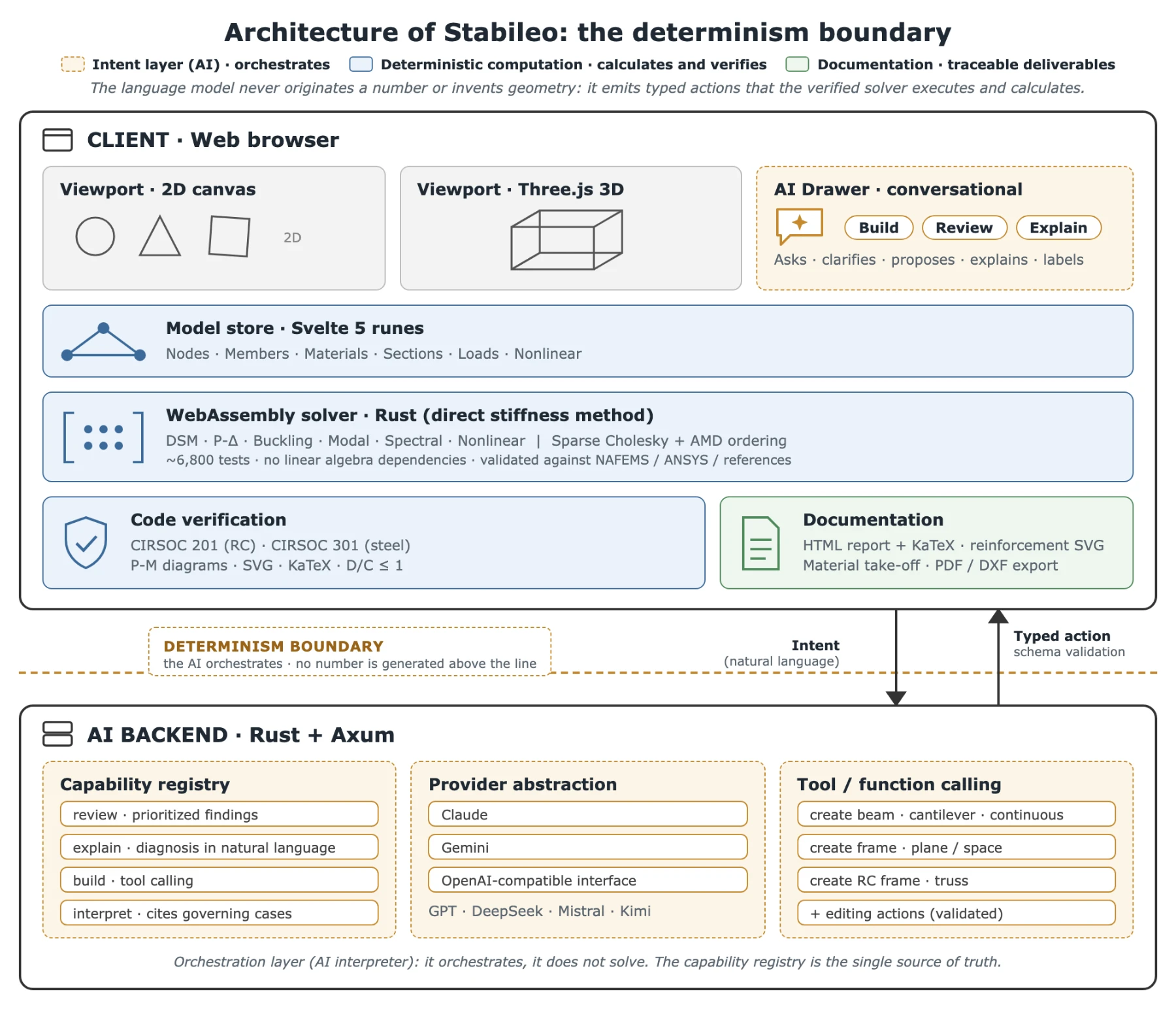
The architecture separates three responsibilities (Figure 1). The intent layer is the AI agent: it interprets natural language, asks clarifying questions and emits typed actions. The deterministic computation layer gathers everything that produces engineering data, that is, the solver that solves, the CIRSOC modules that verify, the generators that expand a typology into a complete model and the drawing ingestion that translates geometry; all of it is reproducible and auditable. The documentation layer produces calculation reports, drawings and quantity take-offs from results already calculated. The rule at the backbone of the system is that the language model never generates a number or invents geometry: both come from deterministic components.
3.2What the boundary guarantees and what it does not
The determinism boundary guarantees that every numerical statement by the agent is traceable to a specific result of the verified solver (combination, station, member); that every AI output is validated against the model schema in the backend and in the frontend before it is imported, rejecting malformed answers or answers with unknown fields; and that, if the AI service is unavailable, the solver, the editor and the checks keep working (safe degradation).
The boundary does not guarantee, on the other hand, that the idealized model is the right one for the real problem, which is an engineering decision, nor that the design is optimal, nor that the loads and assumptions are complete, nor that the code interpretation needs no review. The boundary protects the correctness of the calculation, not the correctness of the intent. That distinction is deliberate and is discussed in §7.
3.3Human oversight: accepting the model before calculating
The agent behaves as a drafting assistant and not as an autonomous executor. The agent proposes a change, the user sees a summary of what is about to be modified and can apply, retry or cancel; and each applied change is a single undo step. Every answer from the agent also carries a visible confidence label stating whether it is advice, an answer based on the solver artifact, a code heuristic or a generated draft. The engineer accepts the model before it becomes active and before adopting any verification conclusion. Human oversight is a fundamental part of the contract.
4Formal verification and fuzzing: towards a proven solver
4.1Motivation
The determinism boundary defined in §3 guarantees that every numerical statement by the agent is traceable to a solver output. That guarantee has, however, a precise limit: the solver is reliable because it is extensively tested, not because it is proven. A test suite, however thorough, covers only the cases its authors imagined. Formal verification and fuzzing are two tools that narrow that gap, one through mathematical proof and the other through systematic exploration of the input space.
The point matters more in the context of use. An AI agent orchestrates the solver: it builds complex models, modifies them over several steps and queries the results to propose new actions. In that loop the solver receives inputs that no engineer reviewed before they reached the engine. If the engine behaves incorrectly in some edge case (a nearly singular stiffness matrix, a degenerate geometry, an extreme load combination), the agent may produce and cite that result without warning. The determinism boundary protects traceability; formal verification protects the correctness of the engine that traceability points to.
4.2What formal verification is
Formal verification is the use of mathematical proof to establish that a system behaves according to its specification for every possible input, and not only for those chosen for testing. The difference from conventional testing is fundamental: testing can find errors; formal verification can prove their absence within the specified domain.
The two main techniques are model checking and theorem proving. Model checking exhaustively explores every state of a finite system and checks that a property holds in each one, and it is the natural tool for communication protocols and hardware circuits. Theorem proving builds a formal logical proof with a proof assistant such as Lean 4, Coq or Isabelle; it is more expressive, handles infinite or continuous systems and is the relevant technique for the numerical algorithms that make up a finite element solver.
Applied to a structural solver, formal verification consists of writing a mathematical specification of the properties the engine must satisfy (for example, that the assembled global stiffness matrix is symmetric positive definite for well-formed elements, that the Cholesky factorization produces an exact decomposition , or that the equilibrium condition applied load holds algebraically) and then proving, with a proof assistant, that the implementation satisfies that specification. If the proof closes, those properties are mathematical guarantees and not empirical conjectures.
This approach is consistent with the practice of formal software verification: just as a formally verified compiler guarantees properties of the code it produces, a formally verified solver guarantees properties of the results it hands to the agent.
4.3What fuzzing is and how it complements formal verification
Fuzzing is a testing technique that automatically generates large volumes of inputs (random, mutated or built according to a strategy) and runs them against the system under test to detect incorrect behavior. Unlike conventional testing, it does not require the author to specify concrete cases: the fuzzer sweeps the input space systematically and reports the inputs that violate a property.
For a structural solver the most relevant variant is property-based fuzzing, in which, instead of comparing the output with an expected value, one asserts mathematical invariants that must hold for any valid input. Some natural properties for a finite element solver are the following.
- Global equilibrium: for any well-formed model, the sum of the reactions equals the total applied load, , regardless of geometry, materials or support conditions.
- Symmetry of the stiffness matrix: is symmetric by construction, .
- Positive definiteness: is positive definite for any statically determinate or indeterminate structure without mechanisms.
- Invariance under rigid-body transformations: translating or rotating a model does not change the internal forces.
The fuzzer generates thousands of valid random models and checks these properties on each one; any model that violates them is a bug. The approach is especially valuable for finding numerical edge cases (nearly singular stiffness matrices, members with very large or very small relative stiffness, degenerate geometries) that a conventional test suite rarely covers.
A second useful variant is differential fuzzing: running the same random model in Stabileo and in a trusted reference, such as OpenSees [2] or analytical solutions for simple cases, and checking that the results agree within a tolerance. It is particularly useful for validating cases outside the standard benchmarks and for detecting regressions as the engine evolves.
Fuzzing and formal verification are complementary. Fuzzing finds the edge cases that then motivate the formal specification: when the fuzzer finds an input that violates a property, that property becomes a candidate for a proof guaranteeing it cannot happen.
5Implementation in Stabileo
5.1The analysis engine and its validation
The engine is written entirely in Rust, with no external linear algebra dependencies (the Cholesky factorization, the orderings, the eigensolvers and the matrix routines are implemented from scratch), which allows it to be compiled to WebAssembly and run locally in the user's browser, with no calculation server. The engine's capabilities cover linear 2D and 3D analysis, geometric nonlinearity (P-Δ, buckling, corotational), dynamics (modal, spectral, time integration) [18] and a variety of elements (frame, truss, cable, plates and shells). At the latest reading of the repository, the engine's validation suite reports on the order of 6,800 tests passing with zero failures, and it was checked against commercial programs such as STAAD.Pro on the same models, reproducing their results with differences below 0.1%, a performance in line with the state of the art.
5.2CIRSOC code verification (scope in concrete and steel)
The Argentine codes differ from the international standards they derive from. CIRSOC 201-2005 [9], based on ACI 318-05, and CIRSOC 301-2017 [10], based on AISC 360-10, include adaptations to the local context.
The reinforced concrete module (CIRSOC 201) is implemented both in the Rust engine and in the frontend verification layer, with auditable step-by-step output and dedicated test coverage. It covers singly and doubly reinforced flexure (with minimum reinforcement), shear, columns under combined flexure and compression through the interaction diagram, slenderness through moment magnification, torsion, biaxial bending, one- and two-way slabs, and serviceability checks. For example, the minimum flexural reinforcement satisfies
shear stirrup design follows
moment magnification for slenderness follows
with , and biaxial bending follows Bresler's reciprocal load formula:
The steel module (CIRSOC 301) is implemented in TypeScript in the frontend verification layer. There is not yet an equivalent module in the Rust engine. The module takes the internal forces produced by the solver and applies the code provisions to the output already calculated (tension, compression with buckling according to KL/r, flexure with lateral-torsional buckling, shear and the H1 combined interaction). Unlike the concrete module, this logic did not yet have a dedicated test suite at the time of writing, so its maturity is preliminary; it is reported explicitly as such so as not to credit it with a degree of validation it does not yet have.
5.3The agent's typed actions
The agent is not a generic conversational assistant but a set of four discrete capabilities, each with its own input and output contract:
- Model review, which produces prioritized findings on the solver artifact.
- Explanation of diagnostics in natural language.
- Model building through tool calling.
- Interpretation of results, which answers by citing the governing cases.
The builder works through a conversational loop. First, the user states an intent. Second, the agent clarifies and emits a typed call (for example, an action that creates a frame with its span and height as parameters). Third, the backend runs a deterministic generator that expands it into a complete model. Then the model appears as a preview and the user approves, modifies or cancels it.
Nine deterministic generators cover the most frequent typologies: simple beams, cantilevers, continuous beams, plane and space frames, multi-bay and multi-story frames, trusses and reinforced concrete frames. On an existing model, a set of editing actions can add a bay or a story, change section families, change the support strategy, add or remove loads and delete members with a structural integrity check.
A capability registry in the backend describes each action with its parameters, types, ranges, defaults and limitations, and serves as the single source of truth: it feeds the model prompts, validates inputs before the action runs and describes the available surface to the frontend. The service supports models from several providers (Claude, OpenAI, DeepSeek, Mistral, Kimi and Gemini) through native adapters and an OpenAI-compatible interface, with the tool calling contract normalized across all of them.
5.4Generating the calculation report and the drawings
The system generates calculation reports in HTML with equations rendered in KaTeX, which include SVG drawings of cross-sections with bars, stirrups and dimensions; beam and column elevations with the reinforcement layout; P-M interaction diagrams with the demand point overlaid; material take-offs (concrete volume, steel weight, reinforcement ratio); beam-column joint details; and slab reinforcement drawings. Reports are exported to PDF through the browser's native printing, and the geometry is exported to DXF for bar detailing.
6Case studies
This section goes through the integrated workflow on worked cases. The structural and verification results of §6.1 and §6.3 are actual outputs of Stabileo's solver and CIRSOC 201 module, obtained by running the engine on the models described.
6.1From the request to a verified design: an RC frame corrected when it fails
The engineer describes the target structure in natural language. For example, a reinforced concrete frame with a 6 m span and a 4 m height, fixed bases and a distributed gravity load on the beam. The agent asks the necessary clarifying questions (steel or concrete? fixed or pinned bases? is a lateral load considered?) and emits the action that creates the frame, which the backend expands deterministically into a model with 4 nodes, 3 frame members and 6 free degrees of freedom. H-21 concrete is adopted ( MPa), with an initial 25×40 cm beam, 30×30 cm columns and a distributed load of 30 kN/m on the beam (Figure 2).
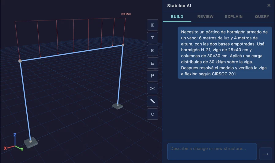
Once Stabileo's solver has run, the vertical reactions are 90 kN per column and global equilibrium holds exactly. The governing bending moment of the beam is kN·m at midspan. The demand/capacity ratio (D/C) compares the demand with the design strength, in this case the ratio , and the member passes when D/C ≤ 1. The CIRSOC 201 flexural check of the 25×40 beam reinforced with 3Ø16 gives a capacity kN·m, that is, D/C = 1.10 > 1: the beam fails. The agent explains the diagnosis citing the values produced by the solver and proposes enlarging the section.
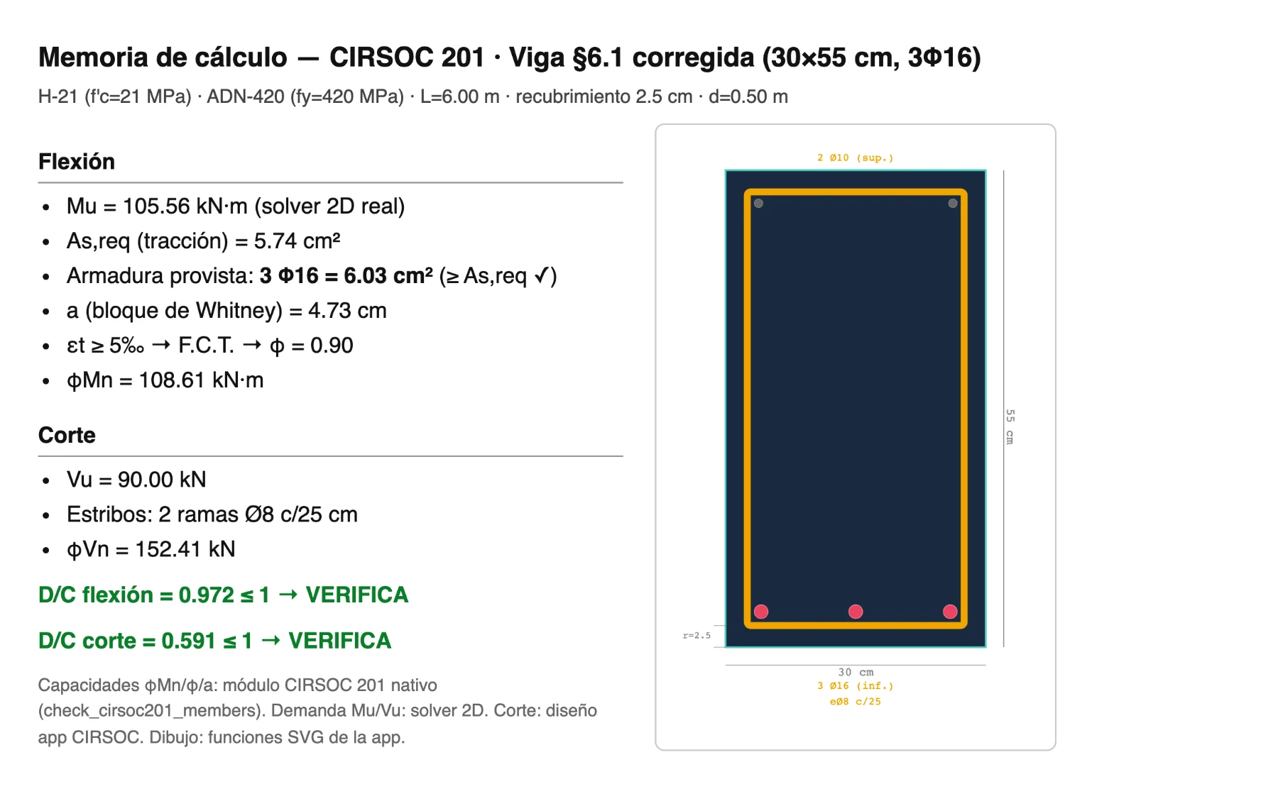
The engineer accepts and the beam becomes 30×55 cm. When the model is solved again, the governing moment of the beam rises to 105.6 kN·m; the new capacity kN·m gives D/C = 0.97 ≤ 1: it now passes (Table 2). An independent hand check reproduces these internal forces and capacities, which supports the traceability of the result. The central point is not the magnitude of the forces, but that every number cited by the agent corresponds to a specific output of the verified solver, and that the decision to enlarge the section is made and signed by the engineer.
| State | Beam section | Reinforcement | [kN·m] | [kN·m] | D/C | Passes |
|---|---|---|---|---|---|---|
| Initial | 25×40 cm | 3Ø16 | 80.8 | 73.3 | 1.10 | No |
| Corrected | 30×55 cm | 3Ø16 | 105.6 | 108.6 | 0.97 | Yes |
Note that the demand moment increases from 80.8 to 105.6 kN·m when the beam is enlarged: in a statically indeterminate frame a stiffer section attracts more moment, so the correct check requires solving the model again and not just recalculating the capacity of the new section. This is precisely where having the solver in the loop adds value, and where an agent that estimated the effect without recalculating would be wrong.
6.2Fast exploration of variants
Once the model exists, trying alternatives is fairly direct. Changing the section family, modifying the support strategy or adding a lateral load per level are expressed as editing actions and run in the browser in seconds. Three variants were applied to the frame of §6.1 and, for each one, the number of actions in each workflow was counted, classified into engineering decisions and mechanical remodeling actions (Table 3). In all three, the agent requires a single decision action and no mechanical actions, whereas the conventional workflow requires the same decision plus five to seven mechanical actions, with an identical structural result. The defensible conclusion is not about time or about a better design: for the same engineering decision and the same result, the agent removes the repetitive mechanical input.
| Variant | Decision (agent) | Mechanical (agent) | Decision (conv.) | Mechanical (conv.) | Result (D/C) |
|---|---|---|---|---|---|
| Change beam 30×55 → 35×65 | 1 | 0 | 1 | 5–7 | 0.97 → 0.88 |
| Fixed bases → pinned | 1 | 0 | 1 | 5–7 | 1.02 (fails) |
| Add lateral load (10 kN/level) | 1 | 0 | 1 | 5–7 | 0.97 |
6.3Modifying a project already calculated: removing a column
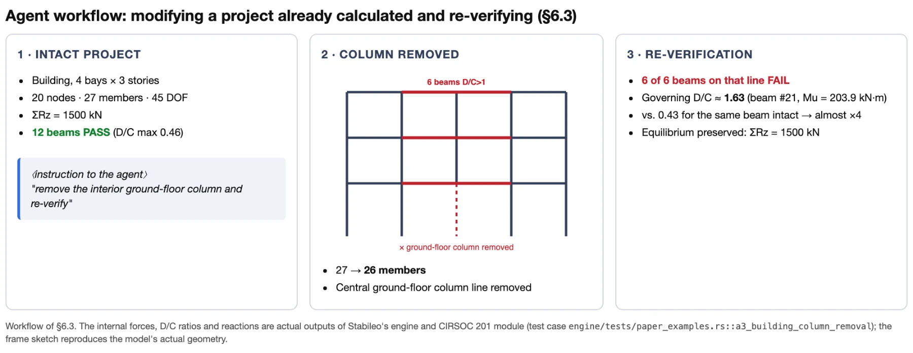
The agent's value becomes clearer when the project has already been calculated and a change comes up. The starting point is a reinforced concrete frame with four 5 m bays and three 3 m stories, fixed bases, H-21 concrete, 25×50 cm beams (4Φ16), 35×35 cm columns and a distributed load of 25 kN/m on every beam (20 nodes, 27 members, 45 free degrees of freedom). Solved and verified, every beam passes the CIRSOC 201 flexural check comfortably: the governing beam has D/C = 0.46.
An architectural decision removes an interior ground-floor column. The engineer states it in natural language; the editing action removes it with a structural integrity check and the model is solved again, with global equilibrium holding ( kN = total load) before and after. The beams that rested on that column now span 10 m and, together with those aligned above them, redistribute the lost support: six beams exceed D/C = 1 and the demand moment of the governing beam almost quadruples, from 54 to 204 kN·m (D/C from 0.43 to 1.63; Figure 3). The agent points out the beams that no longer pass and proposes a deeper transfer section.
Adopting 30×65 cm (5Φ20) for the affected beams and solving again, all of them pass once more (D/C ≤ 0.61; Table 4). What matters is the workflow: a change that by hand requires remodeling, reanalyzing, re-verifying and re-detailing many members is settled as a short conversation, with every number traceable to the solver and subject to the engineer's approval.
| State of the governing beam | Section | [kN·m] | [kN·m] | D/C | Passes |
|---|---|---|---|---|---|
| Intact | 25×50 (4Φ16) | 54.2 | 125.3 | 0.43 | Yes |
| After removing the column | 25×50 (4Φ16) | 203.9 | 125.3 | 1.63 | No |
| Resized | 30×65 (5Φ20) | 189.8 | 313.7 | 0.61 | Yes |
6.4From results to drawings (report, CAD, bar detailing)
The deliverables come straight out of the verified model. The calculation report gathers the model data, the analysis results, member-by-member checks with equations, SVG reinforcement drawings, the P-M interaction diagram and the material take-off. The geometry is exported to DXF for bar detailing. The path runs from intent to drawing without installing software or writing code (Figure 4).
6.5Diagnosing an ill-posed model
The system is also useful when the model is ill-posed. Validation gates reject malformed models (members that reference nonexistent nodes, missing supports that leave a mechanism) and keep the previous model unchanged, showing the precise error. Faced with an unstable structure, the solver flags it. The review capability produces prioritized findings with severity, affected members and suggested corrections, and the explanation capability turns a diagnostic code into guidance in natural language. The agent turns the failure into actionable feedback instead of silently returning a wrong number, which is precisely the risk the determinism boundary seeks to avoid.
7Discussion: impact on professional practice
This work is best read as a continuation rather than a break: CAD took over the mechanical part of drafting and the spreadsheet that of repetitive arithmetic, without taking over judgment; the agent is the next link, which absorbs the mechanical scaffolding (modeling, remodeling, documenting) but leaves judgment with the engineer. Open-source access and running in the browser lower the barrier to entry for students, small firms and academia, and the system's educational mode, which guides the student through the stages of the analysis with the equations in view, extends that benefit to teaching; even so, precision matters, because lowering the barrier to running an analysis does not lower the barrier to interpreting it, so the tool democratizes access and not expertise. The main risk is overconfidence, since a fluent explanation can convey a certainty the model does not justify; this is why the system keeps visible the boundary between what the solver stated and what the agent wrote, with confidence labeling, human acceptance, traceability and safe degradation. None of those measures transfers responsibility: the signed number remains the engineer's.
8Limitations and future work
The conversational agent currently works at the assistance level: it generates beams, regular frames (2D and 3D), trusses and multi-bay, multi-story frames from natural language, and supports editing actions on existing models. It does not, however, iterate a design automatically in search of the lightest or most economical solution. The solver-in-the-loop cycle (in which the agent generates a proposal, solves it, evaluates it and modifies it without human intervention) is on the roadmap but is not implemented. CIRSOC 201 verification is implemented and tested, but the CIRSOC 301 module lives only in the TypeScript frontend layer and does not yet have dedicated test coverage. Native code coverage is limited to CIRSOC 201 and 301; other codes (Eurocode, ACI, AISC) are future work. Customizing report templates per engineering firm is not yet exposed.
As for the reliability of the analysis engine itself, the incorporation of the formal verification and fuzzing presented in §4 is planned in three stages of increasing complexity and horizon. In the short term, the immediate step is to add property-based testing with Proptest, a fuzzing library for Rust, asserting the invariants of equilibrium, symmetry and positive definiteness on randomly generated models. This extension of the existing validation suite requires no architectural changes and significantly increases coverage of the input space beyond the current benchmarks.
In the medium term, the goal is a formal specification of the stiffness matrix assembly core and of the Cholesky factorization in Lean 4, with a proof that the implementation satisfies it. It is a natural thesis topic at FIUBA, at the intersection of civil engineering, computer science and formal methods. The Rust implementation makes the task easier, because its type system already rules out entire classes of memory errors and there is growing tooling for Rust verification, such as Verus and Kani.
In the long term, the vision is a solver whose critical numerical core is formally verified and whose input validation layer is covered by continuous differential fuzzing against references. In that scenario, the determinism boundary stops being an engineering practice and becomes a mathematical guarantee: the agent orchestrates a proven engine, typed actions are validated before they run and every number cited in the calculation report is traceable to a computation whose correctness is proven and not merely tested.
9Conclusions
In contemporary practice, calculation was never the bottleneck: solving linear systems is fast and well understood. The engineer's time goes into the scaffolding around it: modeling, redoing, verifying and documenting. An AI agent can compress that scaffolding if, and only if, it never originates the number: it orchestrates a verified solver that calculates and code modules that verify, and documents by citing those results.
The contributions of this work are the determinism boundary as an architectural principle, its realization in an open-source platform that combines a browser-native solver, CIRSOC verification and an orchestrating AI agent, and an end-to-end demonstration of the workflow, illustrated with a solved case whose internal forces and checks are actual solver outputs, presented with an honest account of what is validated and what is pending. Incorporating generative artificial intelligence into structural calculation is viable when it relies on verified tools and preserves the traceability that professional practice demands. What this work shows is the concrete technical feasibility of that orchestration, on an open, auditable base that runs directly in the browser.
References
- [1]Computers & Structures Inc. SAP2000 Structural Analysis Program. Berkeley, CA, 2024.
- [2]Mazzoni, S., McKenna, F., Scott, M. H., Fenves, G. L. OpenSees: Open System for Earthquake Engineering Simulation. PEER, University of California, Berkeley, 2000.
- [3]Électricité de France. Code_Aster: Analysis of Structures and Thermomechanics for Studies and Research. https://code-aster.org
- [4]Brown, T. B. et al. Language Models are Few-Shot Learners. Advances in Neural Information Processing Systems, vol. 33, pp. 1877–1901, 2020.
- [5]OpenAI. GPT-4 Technical Report. arXiv:2303.08774, 2023.
- [6]Geng, Z., Liu, J., Cao, R., Cheng, L., Frangopol, D. M., Cheng, M. A Novel Multi-Agent Architecture to Reduce Hallucinations of Large Language Models in Multi-Step Structural Modeling. arXiv:2603.07728, 2026.
- [7]Geng, Z., Liu, J., Cao, R., Cheng, L., Wang, H., Cheng, M. A Lightweight Large Language Model-Based Multi-Agent System for 2D Frame Structural Analysis. arXiv:2510.05414, 2025.
- [8]Liu, J., Geng, Z., Cao, R., Cheng, L., Bocchini, P., Cheng, M. A Large Language Model-Empowered Agent for Reliable and Robust Structural Analysis. arXiv:2507.02938, 2025.
- [9]INTI-CIRSOC. Reglamento CIRSOC 201-2005: Reglamento Argentino de Estructuras de Hormigón [Argentine Code for Concrete Structures]. Buenos Aires, 2005.
- [10]INTI-CIRSOC. Reglamento CIRSOC 301-2017: Reglamento Argentino de Estructuras de Acero [Argentine Code for Steel Structures]. Buenos Aires, 2017.
- [11]Yao, S., Zhao, J., Yu, D., Du, N., Shafran, I., Narasimhan, K., Cao, Y. ReAct: Synergizing Reasoning and Acting in Language Models. International Conference on Learning Representations (ICLR), 2023. arXiv:2210.03629.
- [12]Schick, T. et al. Toolformer: Language Models Can Teach Themselves to Use Tools. Advances in Neural Information Processing Systems 36 (NeurIPS 2023), pp. 68539–68551. arXiv:2302.04761.
- [13]Patil, S. G., Zhang, T., Wang, X., Gonzalez, J. E. Gorilla: Large Language Model Connected with Massive APIs. arXiv:2305.15334, 2023.
- [14]Gao, L. et al. PAL: Program-aided Language Models. Proc. 40th International Conference on Machine Learning (ICML), PMLR 202, pp. 10764–10799, 2023. arXiv:2211.10435.
- [15]Abueidda, D. W. et al. Topology optimization of 2D structures with nonlinearities using deep learning. Computers & Structures, vol. 237, 106283, 2020.
- [16]Pfaff, T. et al. Learning Mesh-Based Simulation with Graph Networks. Proc. International Conference on Learning Representations (ICLR), 2021.
- [17]Li, Z. et al. Physics-Informed Neural Operator for Learning Partial Differential Equations. ACM/JMS Journal of Data Science, 2024.
- [18]Chopra, A. K. Dynamics of Structures: Theory and Applications to Earthquake Engineering. 5th ed. Pearson, 2017.
*English translation of the paper presented, in Spanish, at the 29th Argentine Structural Engineering Conference (Jornadas Argentinas de Ingeniería Estructural, JAIE 2026).